Bit Error Test & Arbitrary Waveform Generation
NRZ and PAM Pattern Generators (BPG)
DB Solution BPG instruments support a vast number of speeds, signal types and channel configurations. By extending the binary generators with our remote heads the data rate, the number of levels or both is increased.
The drop down menu below is supposed to help to find the best fitting instrument configuration for your application. Just load the full data sheet by clicking the product number.
| BPG | Remote-Head | Remote-Head Type | Focus | Max. Baud Rate | Max. Channels |
|---|---|---|---|---|---|
| SHF 12105 A | SHF 616 C | PAM-MUX | PAM4 up to 256 Gbps | 128 | 2 |
| SHF 12105 A | SHF C603 B | MUX | NRZ up to 120/128 Gbps | 128 | 4 |
| SHF 12105 A | NRZ up to 60/64 Gbps | 64 | 8 | ||
| SHF 12105 A | SHF C911 A | 67 | 4-Bit DAC | PAM4 up to 120/128 Gbps | 64 | 4 |
| SHF 12105 A | SHF 614 C | 6-Bit DAC | PAM4 up to 120/128 Gbps | 60 | 1 |
| SHF 12125 B | NRZ up to 60/64 Gbps | 60 | 1 | ||
| SHF 12124 B | NRZ up to 32 Gbps | 32 | 2 | ||
| SHF 12126 A | PAM4 up to 64 Gbps | 32 | 1 | ||
| SHF 19120 C | NRZ up to 12.5 Gbps | 12 | 4 |
NRZ and PAM Error Analyzers (EA)
By combining the SHF 11104 A EA with a SHF 11221 A DEMUX, the serial data rate is extended up to 120 Gbps per channel. The SHF 11220 A PAM-Sampler enhances the capability for true PAM4 BER measurements up to a speed of up to 58 GBaud PAM4 (112 Gbps).
Just load the full data sheet by clicking the product number.
| PN | Remote-Head | Remote-Head Type | Max. NRZ Data Rate | Max. PAM4 Baud Rate |
|---|---|---|---|---|
| SHF 11104 A | 64 | 32 | ||
| SHF 11104 A | SHF 11220 A | PAM-Sampler | 64 | 58 |
| SHF 11104 A | SHF 11221 A | DEMUX | 120 | 32 |
Arbitrary Waveform Generators (AWG)
DB Solution is offering a cost effective solution housed in a small and light weight chassis (the SHF 19120 C) and a solution based on our BPG-DAC combination. For PAM signals, it is faster than any other AWG instrument as it samples only one single time per each bit. Thus the baud rate of the resulting PAM signal is as fast as the sample rate of the system.
Just load the full data sheets by clicking the product number.
| AWG / BPG | Remote Head | Channels | Sample Rate | Vertical Resolution | Sample Memory |
|---|---|---|---|---|---|
| SHF 19120 C | 3* | 2.85 GSa/s | 14 bit | 1 GSa | |
| SHF 12104 A | SHF 614 C | 1 | 60 GSa/s | 4 bit | 1 GSa |
| SHF 12105 A | SHF 614 C | 1 | 60 GSa/s | 6 bit | 8 GSa |
| SHF 12105 A | 2x SHF 614 C | 2 | 60 GSa/s | 4 bit | 8 GSa/channel |
High-Speed Data & Telecommunication Modules
Multiplexers (MUX) & Demultiplexers (DEMUX)
| P/N | Type | Input Data Rate Range | Output Data Rate Range |
|---|---|---|---|
| SHF 602 B | 60 Gbps 4:1 MUX |
1.5… 15 Gbps | 6… 60 Gbps |
| SHF C603 B | 128 Gbps 2:1 MUX |
2… 64 Gbps | 4… 128 Gbps |
| SHF 604 A | 80 Gbps 2:1 Power-MUX |
2… 40 Gbps | 4… 80 Gbps |
| SHF C623 B | 120 Gbps 1:2 DEMUX |
10… 120 Gbps | 5… 60 Gbps |
| SHF 11221 A | 120 Gbps 1:2 DEMUX |
60… 120 Gbps | 30… 60 Gbps |
Digital-to-Analog Converters (DAC)
| P/N | Type | Input | Output | Output Amplitude (typ., FS*) |
|---|---|---|---|---|
| SHF 614 C | 60 GBaud 6-Bit DAC |
1… 60 Gbps at 2 to 6 inputs |
1… 60 Gbaud 4 to 64 levels |
1.5 V single-ended 3 V differential |
| SHF 615 B | 60 GBaud 3-Bit Power DAC |
1… 60 Gbps at 2 or 3 inputs |
1… 60 Gbaud 4 or 8 levels |
2.4 V single-ended 4.8 V differential |
| SHF C911 A | 32 | 32 GBaud 4-Bit DAC |
5… 32 Gbps at 2, 3 or 4 inputs |
5… 32 Gbaud 4, 8 or 16 levels |
0.6 V single-ended 1.2 V differential |
| SHF C911 A | 67 | 67 GBaud 4-Bit DAC |
5… 67 Gbps at 2, 3 or 4 inputs |
5… 67 Gbaud 4, 8 or 16 levels |
0.6 V single-ended 1.2 V differential |
PAM Generation and Sampling (PAM-MUX, PAM-Sampler)
| P/N | Type | Input | Output |
|---|---|---|---|
| SHF 616 C | 128 GBaud PAM4 Multiplexer |
1.5…64 Gbps binary at 4 inputs |
6…256 Gbps PAM4 (3…128 GBaud) |
| SHF 11220 A | 60 GBaud PAM4 Sampler |
60…116 Gbps PAM4 (30…58 GBaud) |
30…58 Gbps binary |
Equalizer
| P/N | Type | Max. Data Rate |
|---|---|---|
| SHF C683 A | Analog FIR Filter | 140 Gbps (70 GBaud) PAM4 70 Gbps NRZ |
Limiting Amplifier
| P/N | Type | Max. Data Rate | Typ. Output Amplitude |
|---|---|---|---|
| SHF C653 A | Limiting Amplifier | 120 Gbps | 600 mV single-ended 1200 mV differential |
RF & Microwave Modules and Instruments
Synthesized Signal Generators (Synthesizers)
| P/N & Data Sheet | Type | Operational Range |
|---|---|---|
| SHF 78124 A | 32 | Synthesized Signal Generator (Synthesizer) | 1… 32.8 GHz |
| SHF 78124 A | 64 | Synthesized Signal Generator (Synthesizer) | 1… 64.0 GHz |
Clock Distributions
| P/N & Data Sheet | Type | Output |
|---|---|---|
| SHF C991 A | 64 GHz Arbitrary Clock Distribution | 7 copies of the incoming clock at different divider ratios |
| SHF C992 A | 64 GHz Clock Distribution | 6 copies of the incoming clock at the same frequency |
| SHF 78123 A | 64 GHz Clock Distribution | 13 copies of the incoming clock at different divider ratios |
| SHF C651 B | 67 GHz Clock Buffer | 2 copies of the input clock (one output 180° shifted) |
| SHF C652 A | 67 GHz 1:2 Clock Buffer | 2 inphase differential copies of the input clock signal. |
Switches
| P/N & Data Sheet | Type | No. of Switching Ports |
|---|---|---|
| SHF C701 A | 50 GHz 2:2 Cross Switch (DPDT) | 2 ↔ 2 |
| SHF C702 A | 50 GHz Dual 2:1 Switch (SPDT) | 2x (1 ↔ 2) |
| SHF C704 A | 50 GHz 4:1 Switch (SP4T) | 1 ↔ 4 |
| SHF C980 A | 60 GHz Switchable Filter Bank | 1 ↔ 4 |
Phase Shifters
| P/N & Data Sheet | Type | Max. Delay | Operational Range |
|---|---|---|---|
| SHF C661 B | Adjustable Phase Shifter | 70 ps | 2… 35 GHz |
| SHF C961 A | Phase Shifter with Clock-Doubler | 70 ps | 30… 60/67 GHz (at the doubled outputs) |
Frequency Dividers & Multipliers
| P/N & Data Sheet | Type | Input | Output |
|---|---|---|---|
| SHF C642 B | f -> f/2 Static Frequency Divider | 2… 60 GHz | 1… 30 GHz |
| SHF C643 A | f -> f/2 Static Frequency Divider | 40… 80 GHz | 20… 40 GHz |
| SHF 1632 A | Frequency Doubler | 13.5… 18 GHz | 27… 36 GHz |
| SHF 2781 A | Frequency Tripler | 19… 27 GHz | 57… 81 GHz |
| SHF 2856 B | Frequency Doubler | 25… 32 GHz | 50… 64 GHz |
Signal Shaping (Filters, Equalizers and Attenuators)
| P/N & Data Sheet | Type | Max. Bandwidth |
|---|---|---|
| SHF C683 A | Analog FIR Filter (Equalizer) | 55 GHz |
| SHF C711 A | Dual Analog RF Attenuator | 50 GHz |
| SHF C712 A | Dual Digital RF Attenuator | 40 GHz |
| SHF C980 A | Switchable Filter Bank | 30 GHz |
| SHF C981 A | Tunable Filter | 65 GHz (Filter Range: 18 GHz) |
Baluns
| P/N | Type | Frequency Range | Phase Balance | Amplitude Balance |
|---|---|---|---|---|
| SHF BLN60 A | Active Balun | 40 MHz... 60 GHz | ≤ 2.5° (up to 50 GHz) | ≤ 0.3 dB |
Limiting Amplifiers
| P/N | Max. Data Rate | Typ. Output Amplitude | Type |
|---|---|---|---|
| SHF C653 A | Limiting Amplifier | 120 Gbps | 600 mV single-ended 1200 mV differential |
RF & Microwave Broadband Amplifiers
| P/N & Data Sheet | Signaling Type | Min. BW | Typ. Gain in dB | Min. P1dB | Min. P3dB |
|---|---|---|---|---|---|
| SHF T850 C | Single-ended | 100 | 11.0 | 10.0 | 10.0 |
| SHF M827 B | 1.0 mm | Single-ended | 70 | 11.0 | 11.5 | 15.5 |
| SHF M804 C | Single-ended | 66 | 22.0 | 12.0 | 16.0 |
| SHF M827 B | Single-ended | 66 | 11.0 | 11.5 | 15.5 |
| SHF S804 B | Single-ended | 60 | 22.0 | 12.0 | 16.0 |
| SHF F840 A | Differential (note 3) | 55 | 11.0 | 10.0 | 10.0 |
| SHF S807 C | Single-ended | 55 | 23.0 | 15.0 | 19.0 |
| SHF M803 A | Single-ended | 55 | 22.0 | 11.0 | 15.0 |
| SHF M833 B | Single-ended | 50 | 12.5 | 13.0 | 18.0 |
| SHF S824 A | Single-ended | 35 | 25.0 | 18.0 | 21.0 |
| SHF D837 C | Differential to single-ended | 35 | 10.0 | 12.0 | 16.0 |
| SHF M834 B | Single-ended | 34 | 15.0 | 16.0 | 20.5 |
| SHF D836 C | Differential to single-ended | 30 | 12.0 | 14.0 | 18.0 |
| SHF P101 A | Single-ended | 25 | 16.0 | 18.0 | 22.0 |
| SHF P100 A | Single-ended | 25 | 18.0 | 13.0 | 17.5 |
| SHF P115 A | Single-ended | 25 | 25.0 | 13.0 | 17.5 |
| SHF S126 A | Single-ended | 25 | 29.0 | 23.0 | 25.0 |
| SHF P101 A | ML | Single-ended | 14 | 16.0 | 18.0 | 22.0 |
RF & Microwave Passive Components
Bias Tees
A RF Bias Tee is a passive electronic component to inject DC (direct current) to a RF transmission line, while simultaneously allowing the passage of RF signals. Due to our air line construction, all SHF bias tees provide resonance-free transmission over the whole specified operating frequency range.
45 GHz
| P/N & Data Sheet | Bandwidth | Max. DC Voltage | Max. DC Current |
|---|---|---|---|
| SHF BT45R | 20 kHz – 45 GHz | ± 16 V | ± 400 mA |
| SHF BT45R | HV100 | 800 kHz – 45 GHz | ± 100 V | ± 400 mA |
| SHF BT45R | HV200 | 4 MHz – 45 GHz | ± 200 V | ± 400 mA |
| SHF BT45R | HC1000 | 100 kHz – 45 GHz | ± 16 V | ± 1000 mA |
| SHF BT45R | HC2000 | 500 kHz – 45 GHz | ± 16 V | ± 2000 mA |
| SHF BT45R | HVC100/1000 | 800 kHz – 45 GHz | ± 100 V | ± 1000 mA |
65 GHz
| P/N & Data Sheet | Bandwidth | Max. DC Voltage | Max. DC Current |
|---|---|---|---|
| SHF BT65R | 50 kHz – 65 GHz | ± 16 V | ± 400 mA |
| SHF BT65R | HV100 | 3 MHz – 65 GHz | ± 100 V | ± 400 mA |
| SHF BT65R | HC800 | 100 kHz – 65 GHz | ± 16 V | ± 800 mA |
| SHF BT65R | HVC100/800 | 3 MHz – 65 GHz | ± 100 V | ± 800 mA |
110 GHz
| P/N & Data Sheet | Bandwidth | Max. DC Voltage | Max. DC Current |
|---|---|---|---|
| SHF BT110R | 50 kHz – 110 GHz | ± 10 V | ± 400 mA |
| SHF BT110R | HV25 | 1 MHz – 110 GHz | ± 25 V | ± 400 mA |
Diplexers
Simplified, a RF Diplexer is a Bias-Tee with a certain bandwidth in the low frequency path. Therefore, it can be used to combine or separate a low frequency (LF) and a high frequency (HF) signal. The main function of a diplexer is to allow the simultaneous transmission or reception of two RF signals over a single transmission line or antenna while ensuring isolation between different frequency bands.
45 GHz
| P/N & Data Sheet | Bandwidth HF-Path | Bandwidth LF-Path | Max. LF Voltage | Max. LF Current |
|---|---|---|---|---|
| SHF DX45R | 90 MHz – 45 GHz | DC – 25 MHz | ± 20 V | ± 400 mA |
| SHF DX45R | HVC50/1000 | 100 MHz – 45 GHz | DC – 25 MHz | ± 50 V | ± 1000 mA |
| SHF DX45R | HVC100/2000 | 100 MHz – 45 GHz | DC – 25 MHz | ± 100 V | ± 2000 mA |
| SHF DX45R | X01 | 1200 MHz – 32 GHz | DC – 600 MHz | ± 50 V | ± 1000 mA |
| SHF DX45R | X02 | 3000 MHz – 40 GHz | DC – 1000 MHz | ± 50 V | ± 1000 mA |
65 GHz
| P/N & Data Sheet | Bandwidth HF-Path | Bandwidth LF-Path | Max. LF Voltage | Max. LF Current |
|---|---|---|---|---|
| SHF DX65R | 90 MHz – 65 GHz | DC – 25 MHz | ± 20 V | ± 400 mA |
| SHF DX65R | HV100 | 90 MHz – 65 GHz | DC – 25 MHz | ± 100 V | ± 400 mA |
110 GHz
| P/N & Data Sheet | Bandwidth HF-Path | Bandwidth LF-Path | Max. LF Voltage | Max. LF Current |
|---|---|---|---|---|
| SHF DX110R | 1 GHz – 110 GHz | DC – 50 MHz | ± 20 V | ± 400 mA |
DC Blocks
45 GHz
| P/N & Data Sheet | Bandwidth | Max. DC Voltage | Max. RF Power |
|---|---|---|---|
| SHF DCB45R | 30 kHz – 45 GHz | ± 25 V | 30 dBm |
| SHF DCB45R | HV100 | 700 kHz – 45 GHz | ± 100 V | 30 dBm |
| SHF DCB45R | HV200 | 3.8 MHz- 45 GHz | ± 200 V | ± 200 V |
65 GHz
| P/N & Data Sheet | Bandwidth | Max. DC Voltage | Max. RF Power |
|---|---|---|---|
| SHF DCB65R | 50 kHz – 65 GHz | ± 16 V | 30 dBm |
| SHF DCB65R | HV100 | 3 MHz – 65 GHz | ± 100 V | 30 dBm |
110 GHz
| P/N & Data Sheet | Bandwidth | Max. DC Voltage | Max. RF Power |
|---|---|---|---|
| SHF DCB110R | 150 kHz – 110 GHz | ± 10 V | 30 dBm |
| SHF DCB110R | HV50 | 1.1 MHz – 110 GHz | ± 50 V | 30 dBm |
Attenuators
Our RF fixed attenuators are designed to reduce the amplitude of a signal with minimal distortion to control signal strength, prevent overloading of sensitive components, or match signal levels between different parts of a system.
SHF Attenuators are in stock and ready to be shipped within a short turnaround time.
67 GHz
| P/N & Data Sheet | Bandwidth | Attenuation |
|---|---|---|
| SHF ATT67 A | 3 dB | DC – 67 GHz | 3 |
| SHF ATT67 A | 6 dB | DC – 67 GHz | 6 |
| SHF ATT67 A | 8 dB | DC – 67 GHz | 8 |
| SHF ATT67 A | 9 dB | DC – 67 GHz | 9 |
| SHF ATT67 A | 10 dB | DC – 67 GHz | 10 |
| SHF ATT67 A | 13 dB | DC – 67 GHz | 13 |
| SHF ATT67 A | 16 dB | DC – 67 GHz | 16 |
| SHF ATT67 A | 20 dB | DC – 67 GHz | 20 |
110 GHz
| P/N & Data Sheet | Bandwidth | Attenuation |
|---|---|---|
| SHF ATT110 A | 3 dB | DC – 110 GHz | 3 |
| SHF ATT110 A | 6 dB | DC – 110 GHz | 6 |
| SHF ATT110 A | 8 dB | DC – 110 GHz | 8 |
| SHF ATT110 A | 9 dB | DC – 110 GHz | 9 |
| SHF ATT110 A | 10 dB | DC – 110 GHz | 10 |
| SHF ATT110 A | 13 dB | DC – 110 GHz | 13 |
| SHF ATT110 A | 16 dB | DC – 110 GHz | 16 |
| SHF ATT110 A | 20 dB | DC – 110 GHz | 20 |
Terminations (50 Ω Loads)
A RF Termination, aka a “RF Load” or a “Dummy Load” is used to absorb RF energy and terminate RF transmission lines or circuits. SHF terminations are 50 Ohm resistive loads perfectly preventing signal reflections and ensuring exact impedance matching within the system.
| P/N & Data Sheet | Bandwidth | Min. Return Loss |
|---|---|---|
| SHF TRM110 A | DC – 110 GHz | 10 dB |
Power Dividers
An RF Power Divider splits an input into two output signals. With SHF power dividers, these outputs maintain perfect amplitude and phase matching. Utilizing a resistive design, the power is evenly divided, resulting in ~ 6 dB loss from the input to one output. SHF power dividers can also operate in reverse configuration as “power combiners.”
The SHF PDV18 A is in stock and ready to be shipped within a short turnaround time.
| P/N & Data Sheet | Bandwidth | Max. Amplitude Difference | Max. Phase Difference |
|---|---|---|---|
| SHF PDV18 A | DC – 18 GHz | 0.5 dB | 2° |
| SHF PDV67 A | DC – 67 GHz | 0.6 dB | 7° |
| SHF PDV110 A | DC – 110 GHz | 1.2 dB | 15° |
DC Feeders
A DC-Feeder is bias tees without the capacitor. Therefore, it provides slightly lower insertion loss in case it is connected to an AC-coupled device which already has a capacitor on its input.
| P/N & Data Sheet | Bandwidth | Max. DC Voltage | Max. DC Current |
|---|---|---|---|
| SHF DF45R | DC – 45 GHz | ± 16 V | ± 400 mA |
| SHF DF45R | HV50 | DC – 45 GHz | ± 50 V | ± 400 mA |
| SHF DF65R | DC – 65 GHz | ± 16 V | ± 400 mA |
| SHF DF65R | HV50 | DC – 65 GHz | ± 50 V | ± 400 mA |
| SHF DF110R | DC -110 GHz | ± 16 V | ± 400 mA |
| SHF DF110R | HV50 | DC -110 GHz | ± 50 V | ± 400 mA |
Linear Equalization Filters
A Linear Equalization Filter can be used to offset signal distortion e.g., resulting from bandwidth limitations. This compensation is achieved through a linearly decreasing insertion loss up to the “Nyquist-Frequency,” counteracting an increase in insertion loss along the signal transmission path, such as in an RF cable. The SHF EQ-Series features a fixed “Nyquist-Frequency” and a fixed “Filter Peaking Value,” rendering these components passive, compact, lightweight, and cost-effective. If a more flexible filter is required, we would kindly like to guide your attention to the active filters in our RF & Microwave Modules Product Section.
| P/N & Data Sheet | Nyquist Frequency | Filter Peaking Value* |
|---|---|---|
| SHF EQ16 A | 1.5 | 16 GHz | 1.5 dB |
| SHF EQ16 A | 3 | 16 GHz | 3 dB |
| SHF EQ16 A | 6 | 16 GHz | 6 dB |
| SHF EQ25 A | 1.5 | 25 GHz | 1.5 dB |
| SHF EQ25 A | 3 | 25 GHz | 3 dB |
RF & Microwave Connectors, Adapters and Cables
Coaxial RF Flange & Sparkplug Launchers
KMCOs coaxial launchers are designed to establish a connection between the PCB within an RF module and the external environment. The RF signal transmission through the housing can be achieved using either a glass bead or a dedicated pin. Our range includes Sparkplug or Falange type launchers, supporting frequencies of up to 110 GHz. These launchers are available with various coaxial interfaces, including 2.92mm (K), 1.85mm (V), or 1.00mm interfaces, providing flexibility to meet different connectivity requirements.
| P/N & Data Sheet | Type | Connector | Gender | Connection to Circuitry via | Bandwidth |
|---|---|---|---|---|---|
| KPC100M311 | Flange Launcher | 1.0 mm | male | Connector Pin (included) | 110 |
| KPC100F311 | Flange Launcher | 1.0 mm | female | Connector Pin (included) | 110 |
| KPC185M302 | Flange Launcher | 1.85 mm / V | male | Glass Bead GB185 | 65 |
| KPC185F302 | Flange Launcher | 1.85 mm / V | female | Glass Bead GB185 | 65 |
| KPC185M301 | Sparkplug Launcher | 1.85 mm / V | male | Glass Bead GB185 | 65 |
| KPC185F301 | Sparkplug Launcher | 1.85 mm / V | female | Glass Bead GB185 | 65 |
| KPC292M302 | Flange Launcher | 2.92 mm / K | male | Glass Bead GB292 | 40 |
| KPC292F302 | Flange Launcher | 2.92 mm / K | female | Glass Bead GB292 | 40 |
| KPC292M301 | Sparkplug Launcher | 2.92 mm / K | male | Glass Bead GB292 | 40 |
| KPC292F301 | Sparkplug Launcher | 2.92 mm / K | female | Glass Bead GB292 | 40 |
Coaxial RF Panel (Bulkhead) Adapters
“Panel Adapters” are coaxial adapters designed for attachment to a panel, facilitating the connection of coaxial interfaces from the inner components of a module or instrument to the external environment. The “Front Panel Adapter” provides a coupling nut on the outside which allows hand tightening without the need for a torque wrench while the “Hermetically Sealed Panel Adapter” is specifically engineered for bulkhead connections in vacuum or cryogenic environments, ensuring a sealed and secure connection for electric circuitry to the external components.
All components are available with either 2.92mm (K) or 1.85mm (V) coaxial interfaces, providing flexibility to suit various connectivity needs. Comprehensive data sheets for each part can be accessed by clicking on the respective part number, enabling users to gather detailed information for their specific requirements.
| P/N & Data Sheet | Type | Outer Conductor | Gender | Inner Connector | Gender | Bandwidth |
|---|---|---|---|---|---|---|
| KPC185MF PA | Panel Adapter | 1.85 mm / V | male | 1.85 mm / V | female | 65 |
| KPC185MM PA | Panel Adapter | 1.85 mm / V | male | 1.85 mm / V | male | 65 |
| KPC185FM PA | Panel Adapter | 1.85 mm / V | female | 1.85 mm / V | male | 65 |
| KPC185FF PA | Panel Adapter | 1.85 mm / V | female | 1.85 mm / V | female | 65 |
| KPC185FSMPMFDPA | Panel Adapter | 1.85 mm / V | female | SMPM | male (fd) | 65 |
| KPC185MF FPA | Front Panel Adapter | 1.85 mm / V | male | 1.85 mm / V | female | 65 |
| KPC185FF HA | Hermetically Sealed Panel Adapter | 1.85 mm / V | female | 1.85 mm / V | female | 65 |
| KPC292MF PA | Panel Adapter | 2.92 mm / K | male | 2.92 mm / K | female | 40 |
| KPC292MM PA | Panel Adapter | 2.92 mm / K | male | 2.92 mm / K | male | 40 |
| KPC292FM PA | Panel Adapter | 2.92 mm / K | female | 2.92 mm / K | male | 40 |
| KPC292FF PA | Panel Adapter | 2.92 mm / K | female | 2.92 mm / K | female | 40 |
| KPC292FSMPMFDPA | Panel Adapter | 2.92 mm / K | female | SMPM | male (fd) | 40 |
| KPC292MF FPA | Front Panel Adapter | 2.92 mm / K | male | 2.92 mm / K | female | 40 |
| KPC292FF HA | Hermetically Sealed Panel Adapter | 2.92 mm / K | female | 2.92 mm / K | female | 40 |
| SMAFF PA | Panel Adapter | SMA | female | SMA | female | 20 |
RF Flexible Cables
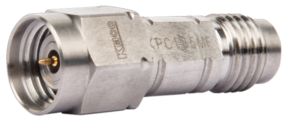
Coaxial RF Adapters
For several years, we collaborate with our Japanese partner, KMCO. Our clients can leverage KMCO’s exceptional proficiency in crafting RF connectors when utilizing our RF adapters. The broad product selection encompasses all coaxial connector interfaces ranging from 18 GHz to 145 GHz of bandwidth.
All in- and between series adapters with 0.8 mm, 1.0 mm, 1.35 mm, 1.85 mm (V), 2.40 mm, 2.92 mm (K), 3.50 mm as well as SMPM (Mini-SMP or GPPO™) can be configured at the link below.
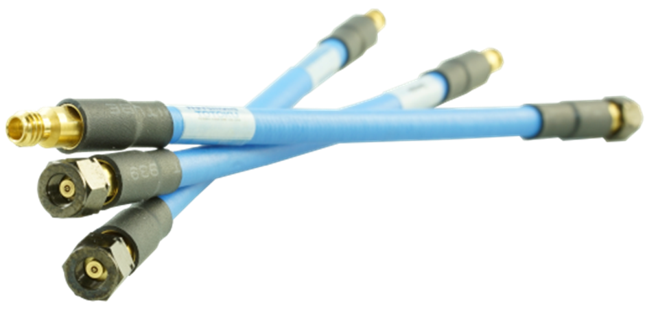
Flexible RF Cables
Totoku’s coaxial TCF cable assembly series demonstrates outstanding flexibility while retaining phase stability across varying temperatures and bending conditions. The remarkably low attenuation is achieved through the utilization of silver-plated copper and E-PTFE with a low dielectric constant. A wide array of options, including precise phase matching (< 1 ps), right-angle connectors, and armoring, are at your disposal.
These cables support all coaxial connector interfaces up to 145 GHz. Custom lengths are available for all cables, catering to the specific requirements of each customer.
Semi-rigid RF Cables
Engineered for frequencies up to 110 GHz our semi-rigid cables are a manually bendable and retain the pre-bent shape until intentionally reshaped. The assemblies listed in the product configurator offer customizable lengths and shapes, making them the optimal solution for large-scale applications and system prototyping. Each cable assembly undergoes precise manufacturing, ensuring excellent physical length accuracy (phase-matched cables are available upon request).
Semi-flexible RF Cables
Compared to other types of coaxial cables (refer to the sections above), the semi-flexible types exhibit the ability to accommodate the smallest bending radius. They require less force for bending compared to its semi-rigid counterparts, making them easily installable in confined spaces through hand shaping at customer’s site. KMCO’s semi-flexible cable assemblies are engineered for frequencies up to 110 GHz, specifically designed for broad-spectrum measurements and system applications. Customization options, including precision phase matching, are also available for all cables, which can be tailored to any customer-specified length.